
Troubleshooting & Tips
Why are my lights flickering?
The simple answer is power. Lumitec’s solid state electronics are tested, sealed, and highly reliable. If flickering occurs after the installation of our lights, especially the higher powered underwater lights, it is most likely due to lack of power being supplied to the light. The most common cause is undersized wire, especially over longer wire runs. Poor connections and the use of wire nuts can also contribute. You can check the light’s operation by connecting it directly to full charged 12V battery. If the flickering stops, start checking the wiring and insure there is at least 10V available at the end of the Lumitec wire.
The lights are designed to operate at constant power- if the voltage drops, the current draw goes up, so be sure to size the wiring and fuse properly. A light that draws 3.6A at 12V will draw 5A at 10V.
What is the correct gauge of wire to use?
Electrical components should always be installed by a knowledgeable and qualified individual. Wire gauge requirements are based on circuit load and configuration and therefore will vary by installation. In all instances the wire gauge should be large enough to accommodate the total circuit load, and correct fusing should prevent over-current events on the circuit. Lumitec lights do not require additional components such as dimmers and proprietary switches. Complete installation instructions for each product are included in each package.
Can I wire my lights in series?
It is not recommended you wire your lights in series as Lumitec lights are designed to work at their optimum with a direct power source. We recommend wiring your light in parallel for best results.
Can I use a third party dimmer switch?
If your lights supports TTP (Time Toggle Protocol) you don’t need one! Lumitec’s ground breaking technology allows you to dim your lights with just a standard on/off switch.
If you really want to add a third party dimmer (3PD), first insure that you selected a Lumitec 3PD compatible light, then you need to use a product that supports 12/24V Pulse Width Modulation (PWM). PWM dims a light by reducing the duty cycle, the time the light is actually on. You can’t see it but the light is cycled off hundreds of times in a second so less light is emitted, creating the dimming effect. Non-PWM dimmers simply reduce the voltage, which is incompatible with Lumitec lights.
Can I bond my lights?
Lumitec does not recommend bonding your lights. Bonding schemes can vary greatly by boat and unless properly designed may do more harm than good. All SeaBlaze housings are electrically isolated from the circuitry so bonding is not necessary.
Why is there Noise coming from my speakers when my lights are on?
Some noise is common on any switching type of power supply due to the nature of the power conversion. As long as there is switching of this type, there will be noise generated. Each of our lights has a switching power supply in it, as is the case with many electronics today. There are several solutions to reduce or eliminate the this noise. We have outlined the best solutions for Lumitec Lights below. As always, please consult a professional on your installation before beginning.
First; separate the power wire running to the lights from any other wiring on vessel. When the power lines touch (are in same conduit, zip tied together, bundled) it can cause transference that is causing the speaker noise. Run across/perpendicular to bundles. 9 out of 10 times this eliminates the noise.
Secondly, you may install a relay between the lights and the shortest distance to the power supply, then connect your switch to the relay. Separate all power wires to the lights from any other wiring on the vessel. The Relay should be rated for approximately 20% more than the total amp draw of the lights being installed. The circuit should be fused properly based on approximately 20% more than the total amp draw of the lights (in-line, fused bus bar, fused circuit breaker are all acceptable depending on you installation).
Lastly, or in addition to the above; try putting a 4700 µF Electrolytic Capacitor across the positive and negative power terminal at the back of the amplifier (or radio). As long as you get one that is 35V or higher, and over 4700 µF, it ought to do the trick. The capacitor has a polarity marking (stripe with - symbol goes to the negative terminal) so be sure not to connect it backwards.
Useful Diagrams
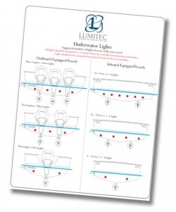
Underwater Light Placement Guide
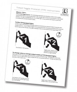
TTP Operation Guide
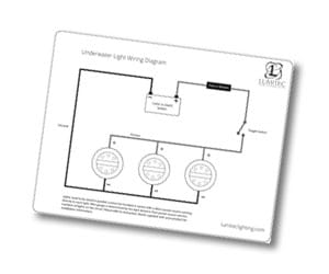
Underwater Light Wiring Diagram